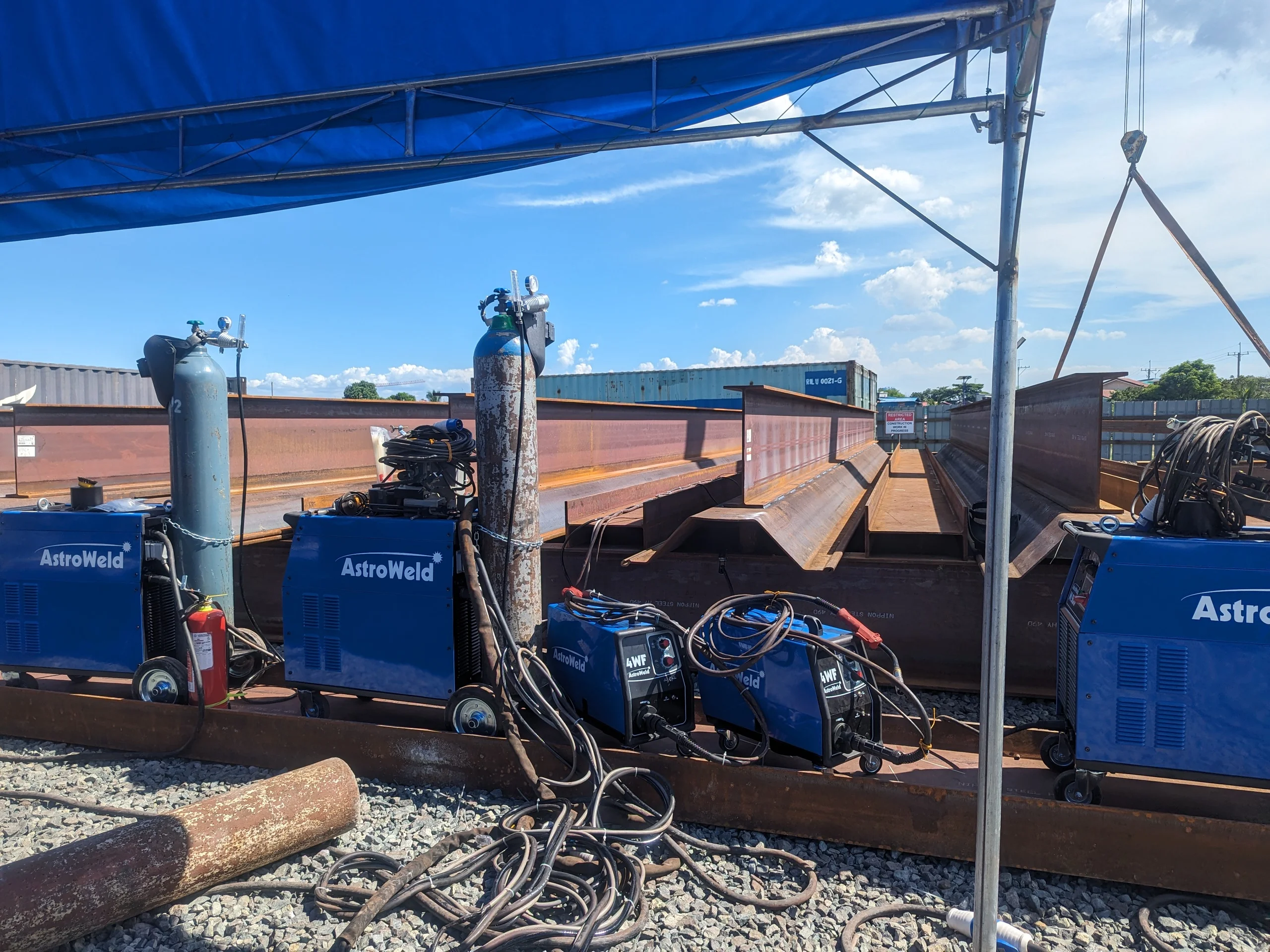
PROJECT OVERVIEW
The Hat H Sheet Pile fabrication project involved the production of large structural steel sheet-pile assemblies requiring repetitive fillet welding.
The application used SP-10H (SYW295) sheet-pile material and SM490A H-beam material. The sheet-pile material thickness was 10.8 mm, with the welding joint specified as a lap joint with a fillet weld. The pre-WPS specified an 8.1 mm leg length and 5.7 mm throat.
The project used Flux-Cored Arc Welding (FCAW) with an AstroWeld M500 welding machine and a Gullco MOGGY welding carriage.
The objective was not simply to introduce welding automation. The production requirement was to achieve a more controlled and repeatable welding operation while handling a high volume of repetitive sheet-pile assemblies.
MATERIAL
Two materials were joined in the sheet-pile assemblies, as specified in the project pre-WPS:
- SP-10H (SYW295) — sheet-pile material, 10.8 mm thick
- SM490A — H-beam material
The joint was a lap joint with a fillet weld. The pre-WPS specified an 8.1 mm leg length and 5.7 mm throat.
The documented procedure references AWS D1.1/D1.1M:2020 as the code basis for the project procedure.
WELDING PROCESS
The project used Flux-Cored Arc Welding (FCAW) as the welding process. The pre-WPS defined the process characteristics: DCEP (+) polarity, spray arc transfer mode, and 100% CO₂ shielding gas.
The process was operated mechanized: the welding gun was mounted on a Gullco MOGGY carriage that controlled the welding movement along the joint. This approach introduced mechanization into the welding operation without requiring a complete robotic welding cell.
Why mechanization mattered on this project: the work was highly repetitive, so welding time, weld consistency, and consumable consumption were the production factors that determined whether the job ran profitably.
EQUIPMENT
The project used a mechanized FCAW arrangement — the power source provided the welding energy, the wire-feeding system delivered the consumable, and the carriage controlled the gun movement:
The operator remained responsible for setup, joint positioning, welding control, monitoring, and repositioning, while the carriage controlled the welding movement along the joint.
CONSUMABLES
The specified consumable, as documented in the project pre-WPS:
- BÖHLER E71T-1C-H8 — flux-cored wire, 1.2 mm diameter
- Classification: AWS A5.20 / EN ISO 17632-A
- Shielding gas: 100% CO₂ at 15 L/min
The E71T-1C-H8 designation indicates a flux-cored wire with CO₂ shielding and a low-hydrogen (H8) classification — a combination well suited to repetitive structural fillet welding under a documented procedure.
WELDING PARAMETERS
The electrical and shielding-gas parameters below are taken directly from the project pre-WPS.
PRE-WPS PARAMETERS
| Parameter | Value |
|---|---|
| Welding process | FCAW |
| Welding position | Horizontal / PB / 2F |
| Polarity | DCEP (+) |
| Transfer mode | Spray arc |
| Current | 196–256 A |
| Voltage | 25.4–28.4 VDC |
| Shielding gas | 100% CO₂ |
| Gas flow | 15 L/min |
| Technique | Stringer bead |
| Passes | Single |
| Oscillation | None |
| Preheat | None |
| Weld configuration | 200 mm intermittent weld / 500 mm pitch |
| Procedure basis | Project pre-WPS / AWS D1.1/D1.1M:2020 |
Electrical and shielding-gas parameters taken directly from the project pre-WPS.
PRODUCTION METHOD
The production method combined a documented procedure with mechanized torch movement:
- The pre-WPS defined the process, consumable, electrical characteristics, shielding gas, position, and weld configuration for every assembly.
- The specified weld was intermittent — 200 mm weld length on a 500 mm pitch, single pass, stringer bead, no oscillation, no preheat.
- The Gullco MOGGY carriage moved the gun along the joint at a controlled travel speed, giving repeatable weld size and profile across hundreds of assemblies.
- The operator set up each joint, positioned the carriage, controlled the weld start and stop, monitored the bead, and repositioned the carriage for the next weld.
PRODUCTION DATA
The recorded production data covered ten weeks. The weekly table below reproduces the project records — every value is Recorded.
WEEKLY PRODUCTION AND CONSUMABLE RECORDS
| Week | Pile Sets | Wire Rolls |
|---|---|---|
| 1 | 55 | 15 |
| 2 | 86 | 26 |
| 3 | 97 | 30 |
| 4 | 114 | 35 |
| 5 | 112 | 35 |
| 6 | 73 | 20 |
| 7 | 70 | 5 |
| 8 | 35 | 10 |
| 9 | 7 | 25 |
| 10 | 12 | 21 |
Recorded (observed) production data from the project records.
WEEKLY OUTPUT — MECHANIZED VS MANUAL PERIODS
The same recorded values as a chart. Weeks 1–5 cover the mechanized welding period; weeks 6–10 cover the manual FCAW period that followed the change in welding personnel. All values are recorded — no calculated or target figures appear in this chart.
Pile sets per week, scaled to the Week 4 peak of 114. All values recorded from project production records.
The project records identify 649 completed pile sets and 176 rolls of wire consumed in the recorded production period — both recorded figures. The records also identify 818 remaining pile sets and a calculated requirement of 222 rolls for the remaining work, giving a calculated total wire requirement of 398 rolls for the project as a whole.
PROBLEM
Two distinct problems emerged during production, both visible in the records.
Problem 1 — Production declined after the change to manual welding. The production operation changed to manual FCAW when welding personnel changed and the replacement welders were not familiar with operating the welding carriage. Output then declined week by week: 73, 70, 35, 7, and 12 sets in Weeks 6 through 10 — against 86, 97, 114, and 112 sets in the mechanized Weeks 2 through 5.
Problem 2 — Weld dimensions increased beyond the specified target. The production analysis identified weld sizes larger than the pre-WPS target: an observed leg length of approximately 11–12 mm against the specified 8.1 mm, and an observed seam length of approximately 23 cm against the 20 cm calculation basis. The analysis calculated this as a +35.8% leg length increase and a +15% seam length increase.
The consequence was calculated in the production analysis: the estimated wire requirement for the original 20 cm / 8.1 mm configuration was 258 rolls, while the larger 11–12 mm / 23 cm configuration resulted in a calculated requirement of 498 rolls.
The 258 and 498 roll figures are calculated requirements in the production analysis — not actual consumption. The same report records 176 rolls actually consumed for the 649 completed sets.
ROOT CAUSE
The project records point to two contributing factors, stated here in the language of the source material:
- Operator unfamiliarity with the mechanized system. When welding personnel changed, the replacement welders were not familiar with operating the welding carriage. As a result, the operation reverted to manual FCAW — and the records show production declined.
- Weld size exceeding the specified target. The production analysis documented leg and seam dimensions larger than the pre-WPS target, which increased the weld metal deposited on every assembly and, in the analysis, the calculated wire requirement.
The project records do not attribute the production decline to equipment capability. The AstroWeld M500 and Gullco MOGGY had already demonstrated their capability in Weeks 2–5. The records describe the decline as a consequence of the operation reverting to manual welding without operator familiarity with the mechanized system.
CORRECTIVE ACTION
The corrective measures documented with the project are analysis and control measures rather than a single fix:
- Weld-size and consumable analysis. The production analysis quantified the effect of the larger welds — the +35.8% leg length and +15% seam length increases — and their impact on calculated wire requirements, making the cost of uncontrolled weld size visible.
- Proposed welding performance monitoring. The project documentation proposed a welding performance monitoring form recording welder information, welding process, set number, start time, finish time, total welding time, and comments — so weld time, wire consumption, and output could be tracked per set.
- Operator training on the mechanized system. The documented lesson is that mechanized capability must be supported by operators trained to set up and run the carriage, and by a controlled production process.
RESULTS AT A GLANCE
The results below are taken directly from the project records and the production analysis. Each value is tagged Recorded (observed production data), Calculated (engineering analysis), or Pre-WPS Target (specified requirement).
649
176 rolls for 649 sets
114 pile sets (Week 4)
86 / 97 / 114 / 112 sets
73 / 70 / 35 / 7 / 12 sets
818 (from project records)
+35.8% (8.1 mm basis to 11–12 mm observed)
+15% (20 cm basis to 23 cm observed)
258 rolls
498 rolls
8.1 mm
5.7 mm
LESSONS LEARNED
The project revealed that welding production depends on more than the welding machine. Four elements must work together:
1. EQUIPMENT
The AstroWeld M500 provided the FCAW welding power, while the Gullco MOGGY provided mechanized torch movement.
2. WELDING PROCEDURE
The pre-WPS established the welding process, consumable, electrical characteristics, shielding gas, position, weld configuration, and other procedure requirements.
3. OPERATOR CAPABILITY
Operators must know how to set up and operate the mechanized carriage correctly. The production experience demonstrated the consequence of changing welders without sufficient familiarity with the mechanized system: the operation reverted to manual FCAW and production decreased.
4. PRODUCTION CONTROL
Weld size, welding time, wire consumption, and output need to be monitored. The project documentation proposed a welding performance monitoring form recording welder information, process, set number, start and finish times, total welding time, and comments.
KEY TAKEAWAY
The Hat H Sheet Pile project demonstrates a practical lesson in welding mechanization:
Productivity is not achieved by equipment alone. It comes from the combination of the right welding process, correctly configured equipment, controlled weld movement, trained operators, and production monitoring.
The project showed a clear production difference between the period using mechanized welding and the subsequent period using manual FCAW. At the same time, the production records identified increases in weld dimensions that affected calculated welding-wire requirements.
For repetitive structural welding, mechanization can provide a means of controlling the welding movement and improving repeatability. But to capture that benefit consistently, operators must be trained to use the equipment and the welding procedure must be followed.
Control the process. Control the weld. Control the production.